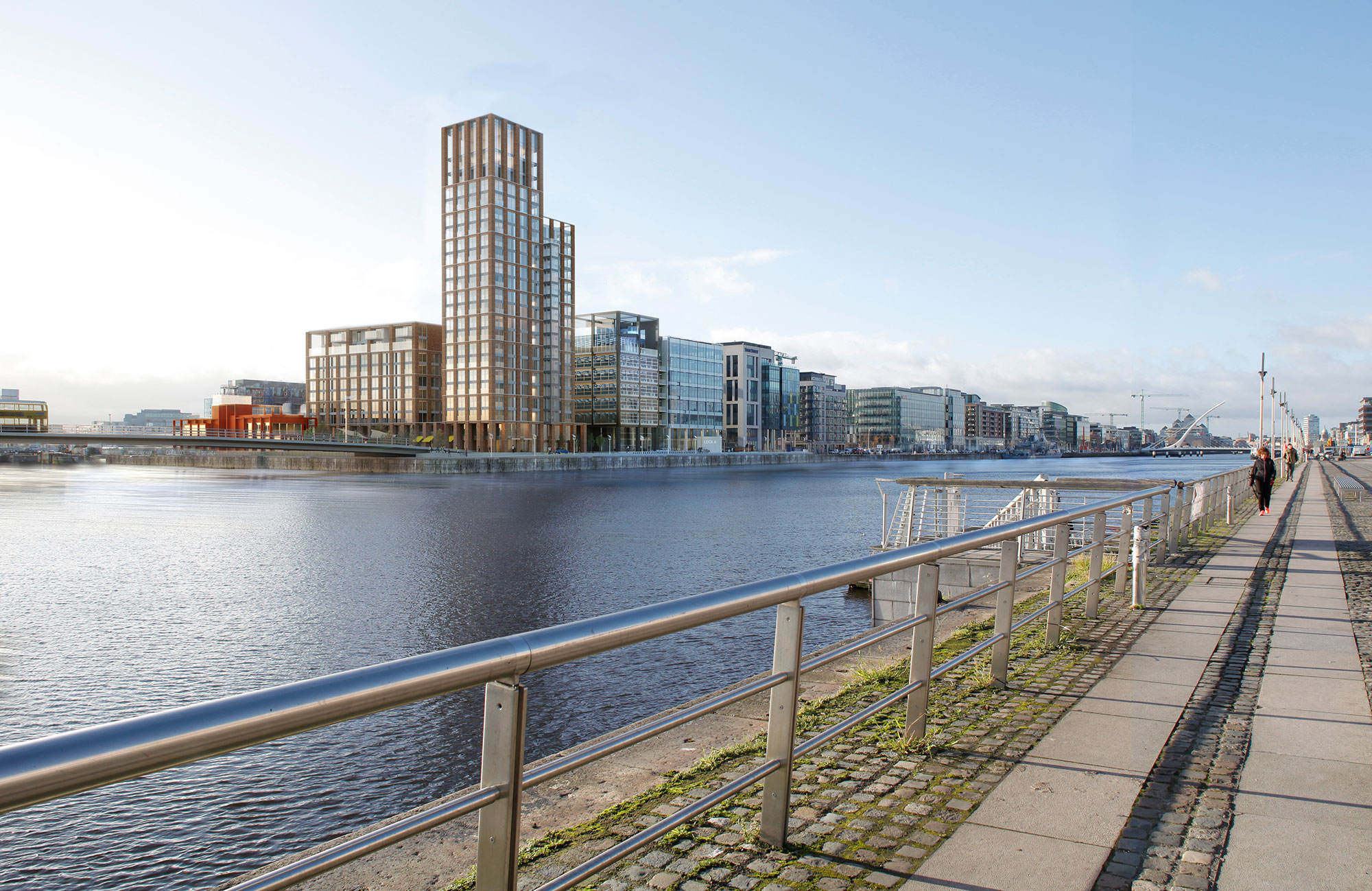

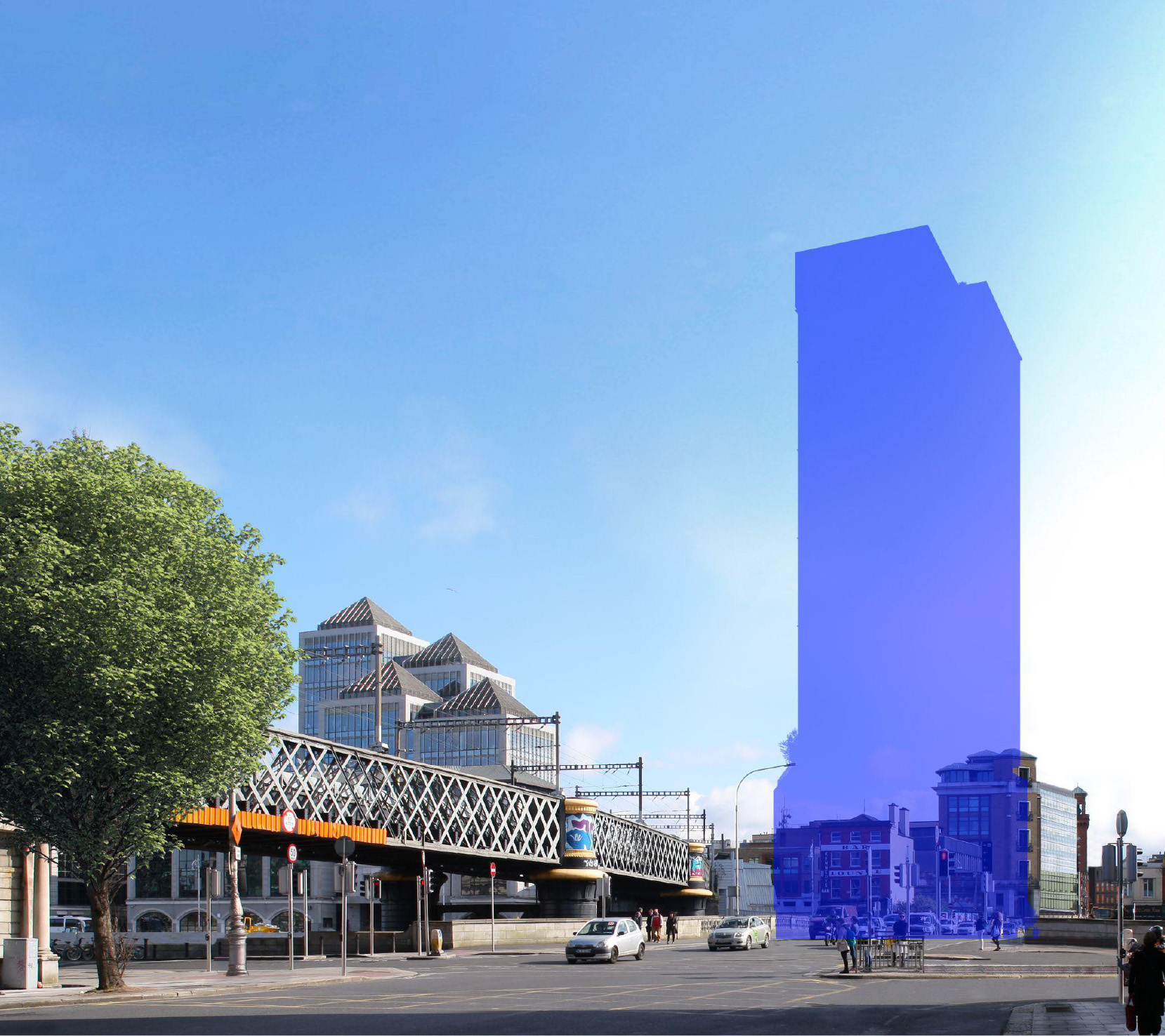
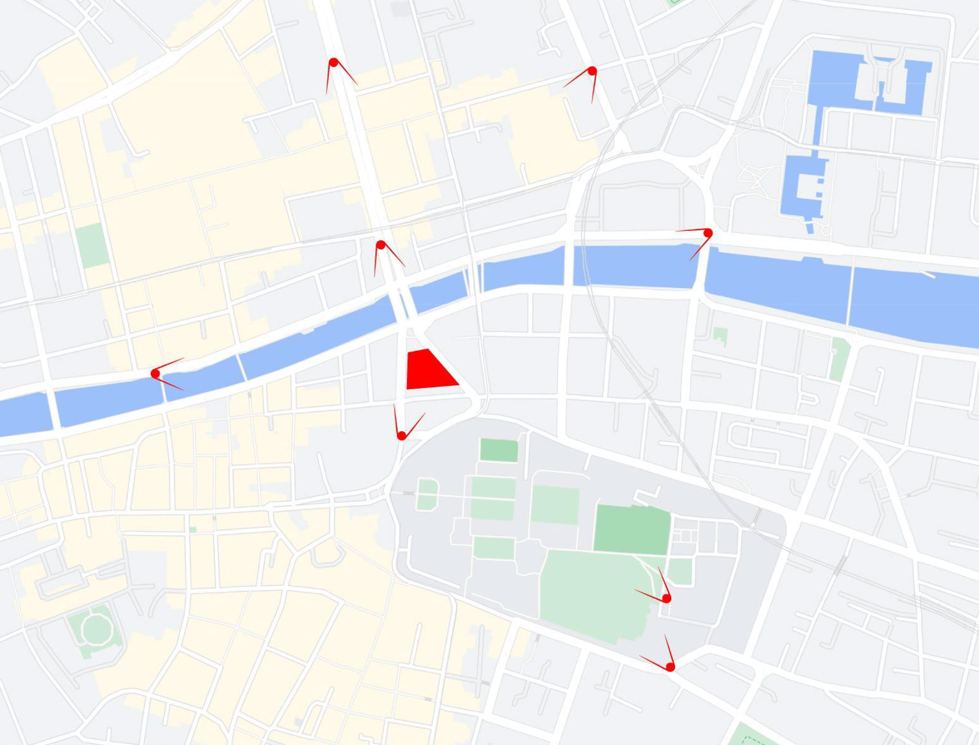
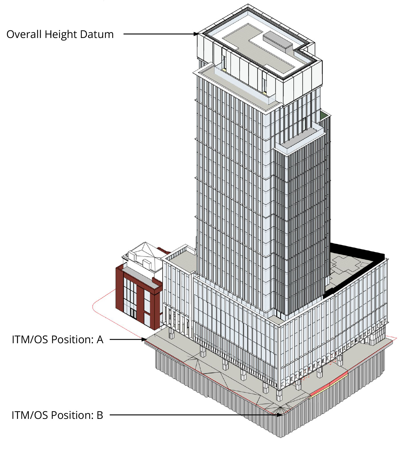
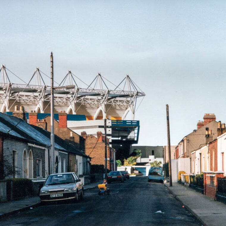
AVR 0 - Location and size of proposal
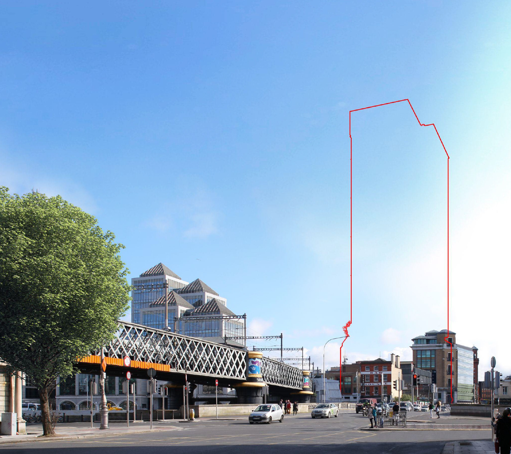
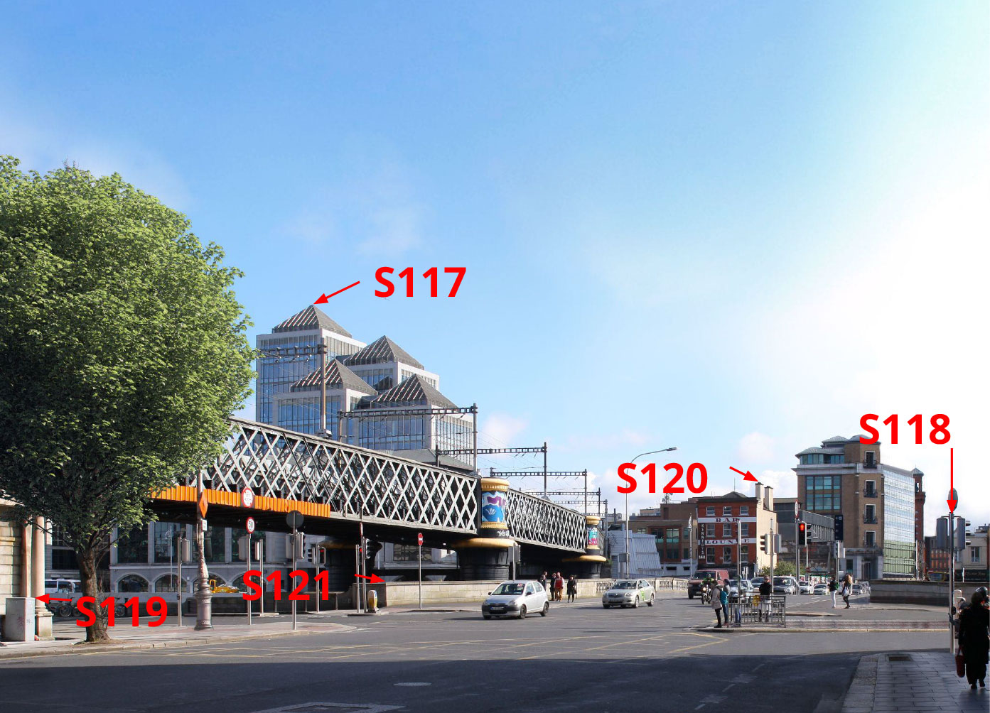
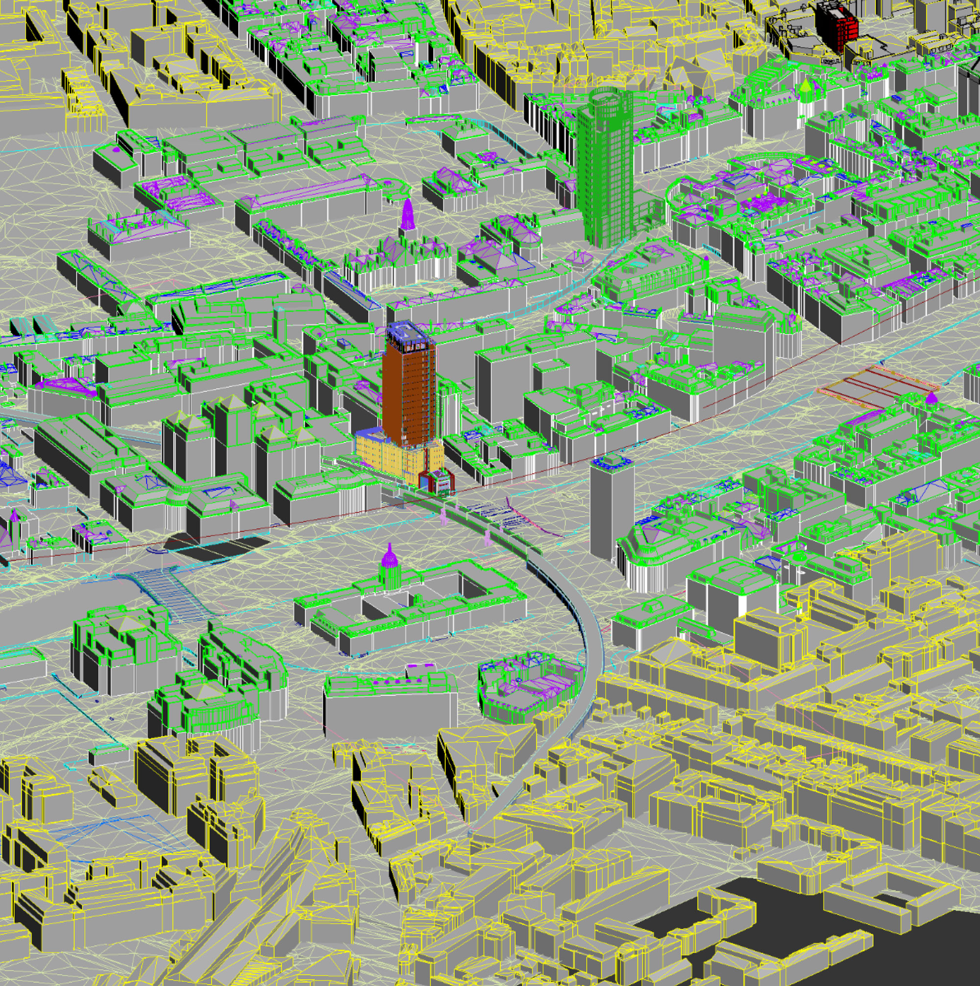
AVR 1 - AVR 0 + Visibility of proposal

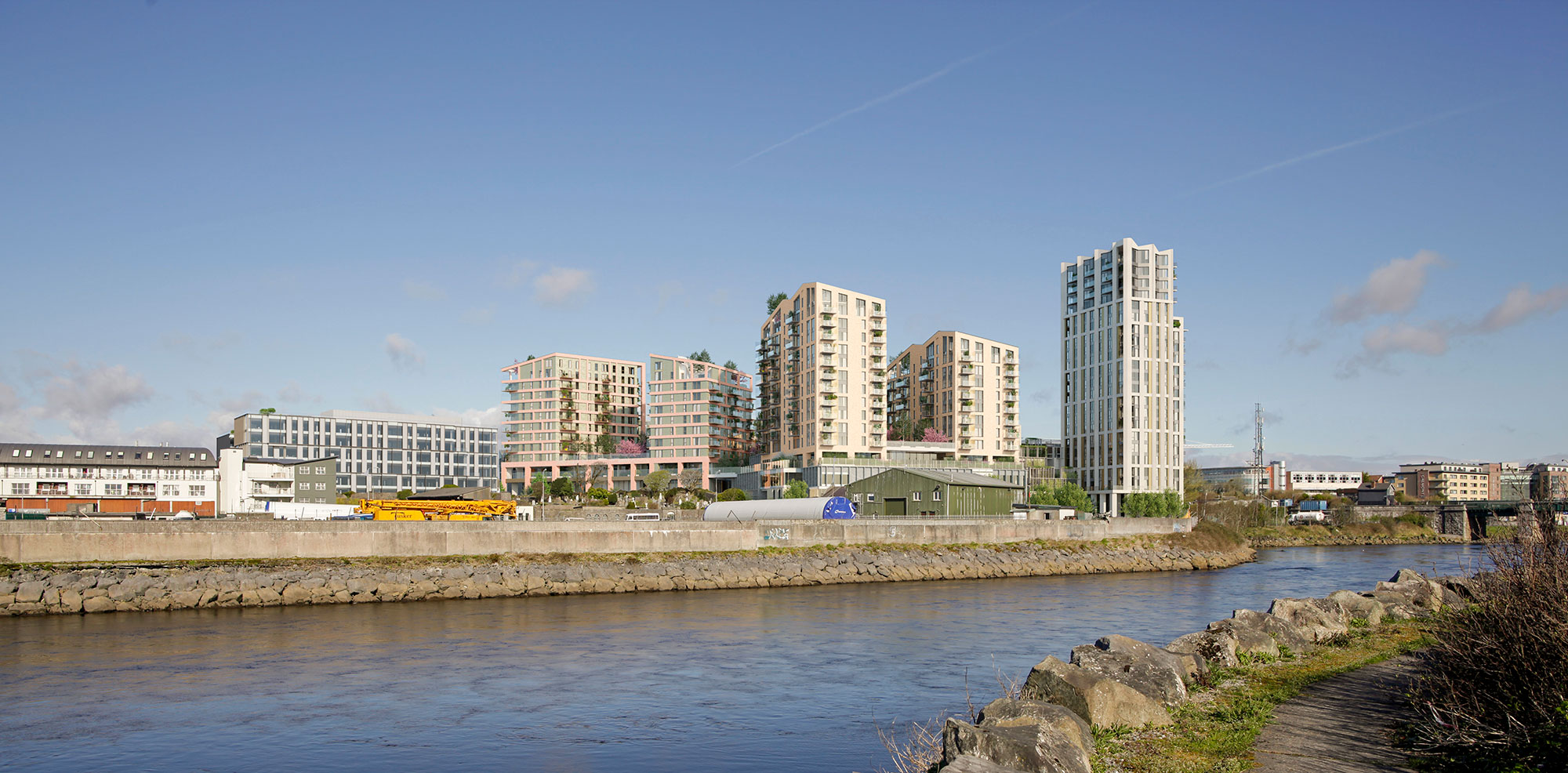
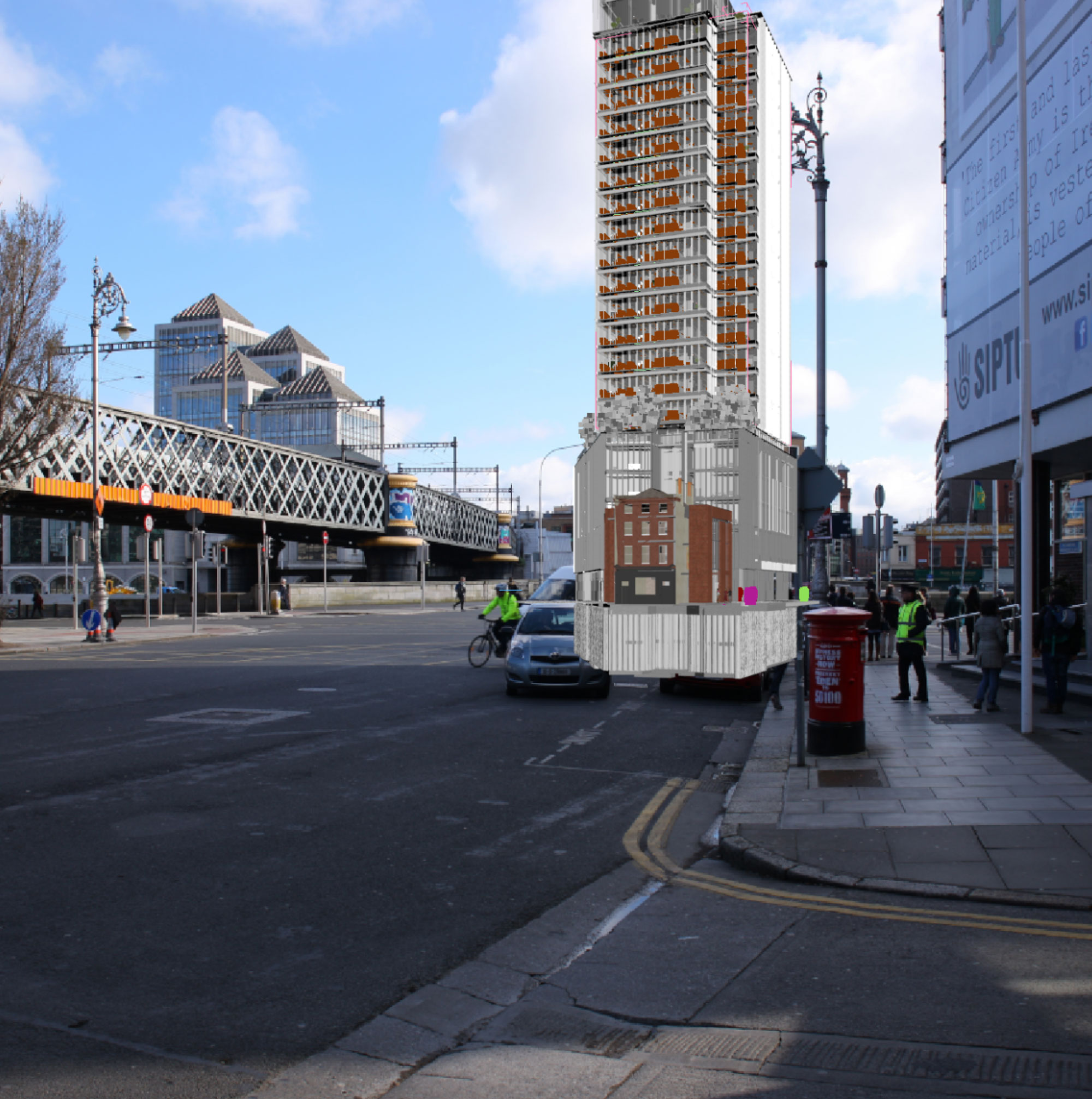
AVR 2 - AVR 1 + Architectural form
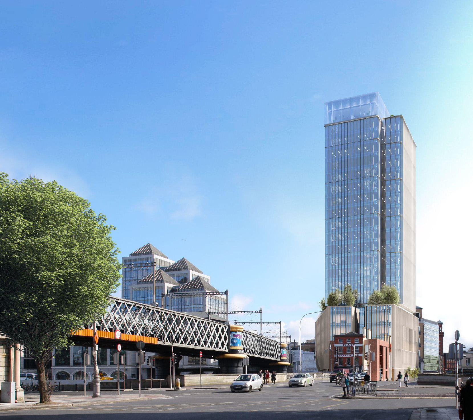
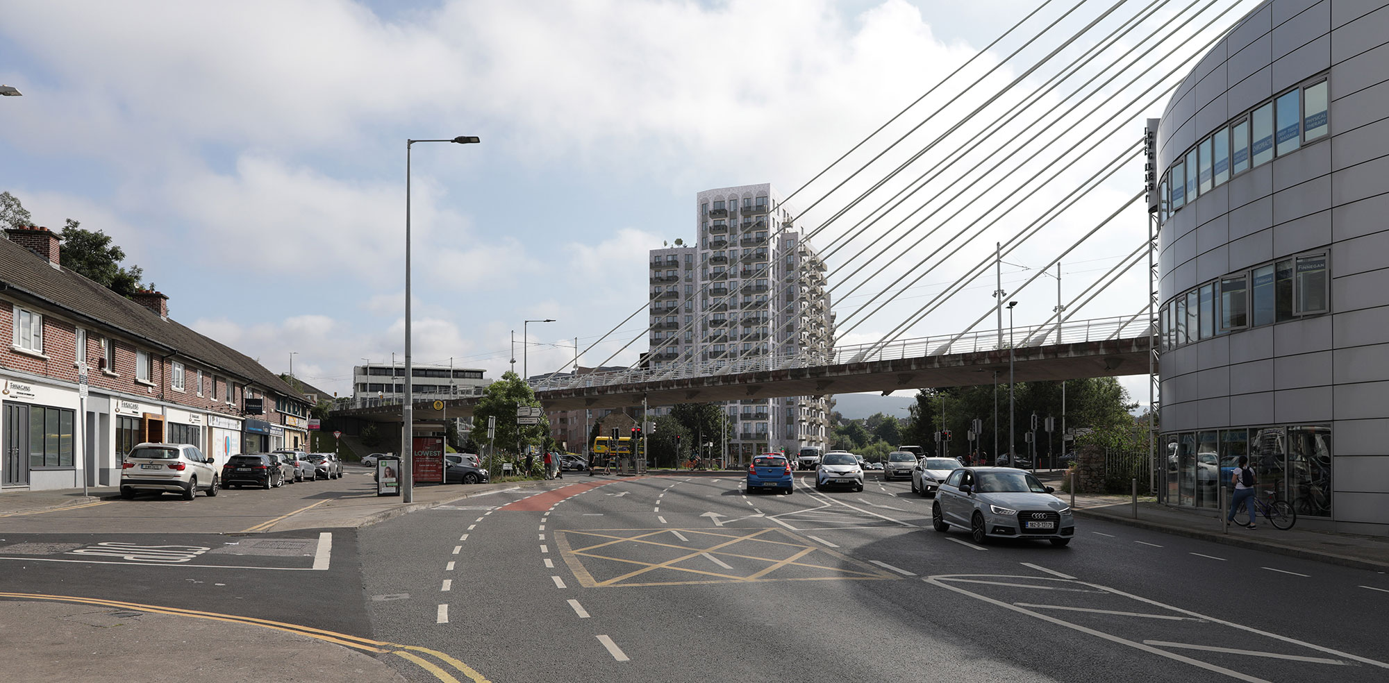
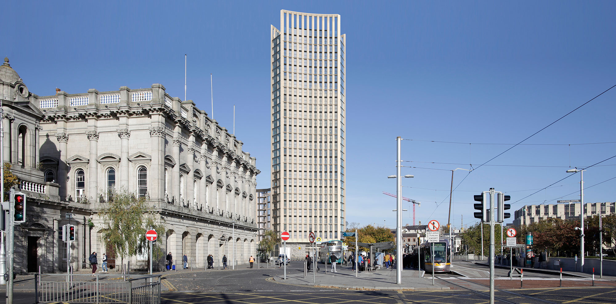
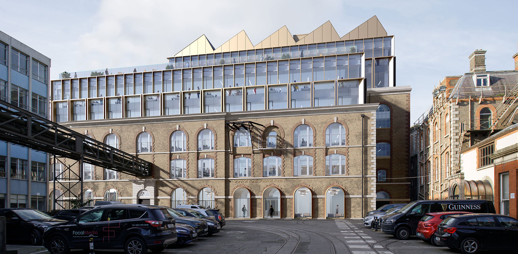
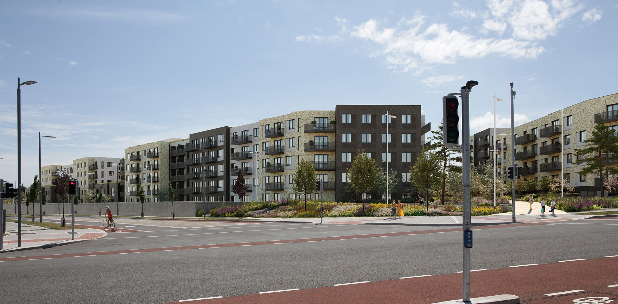
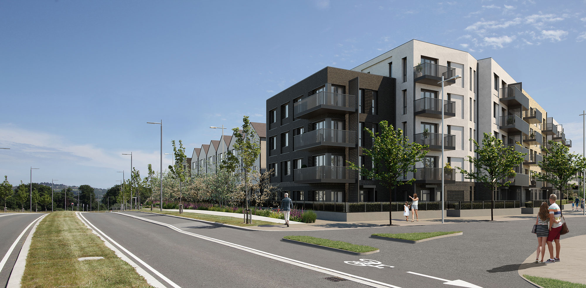
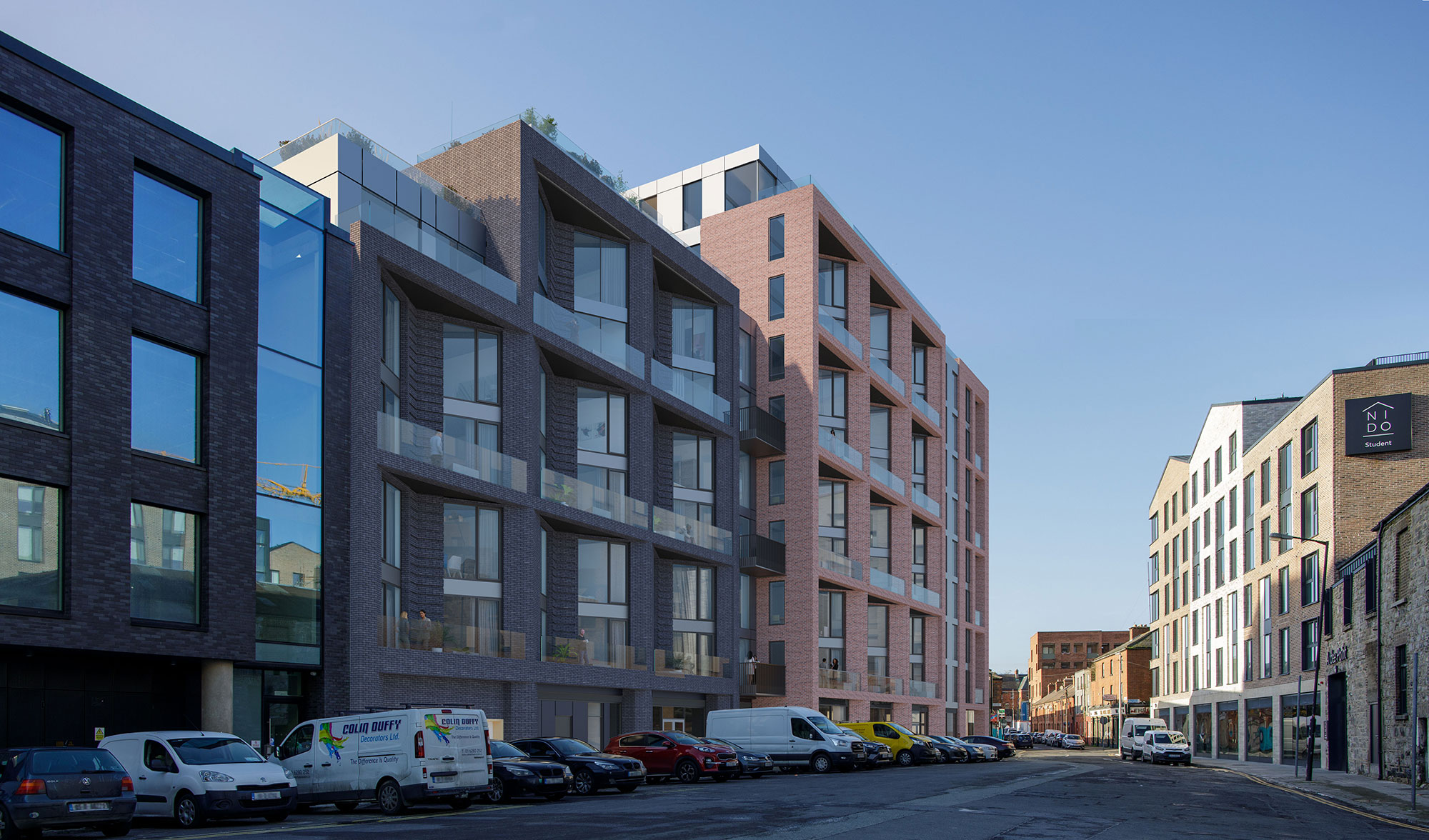
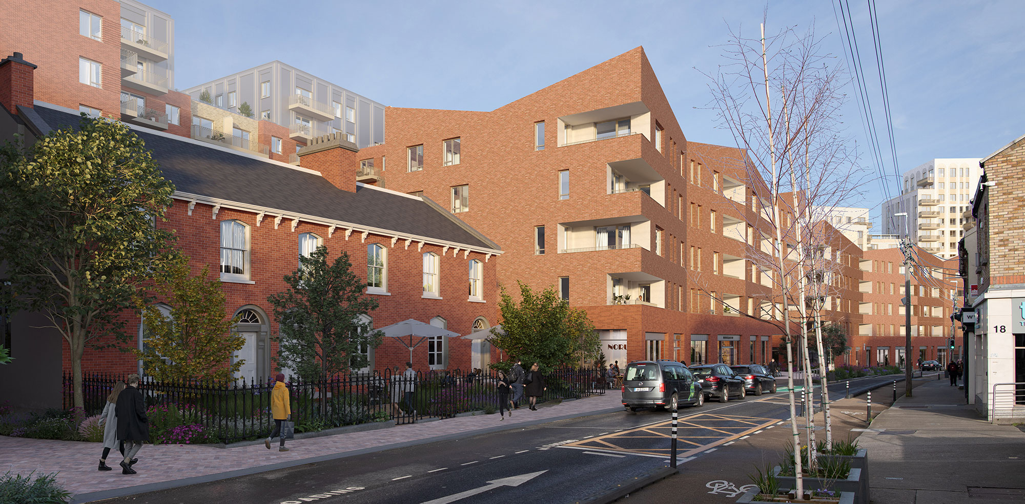
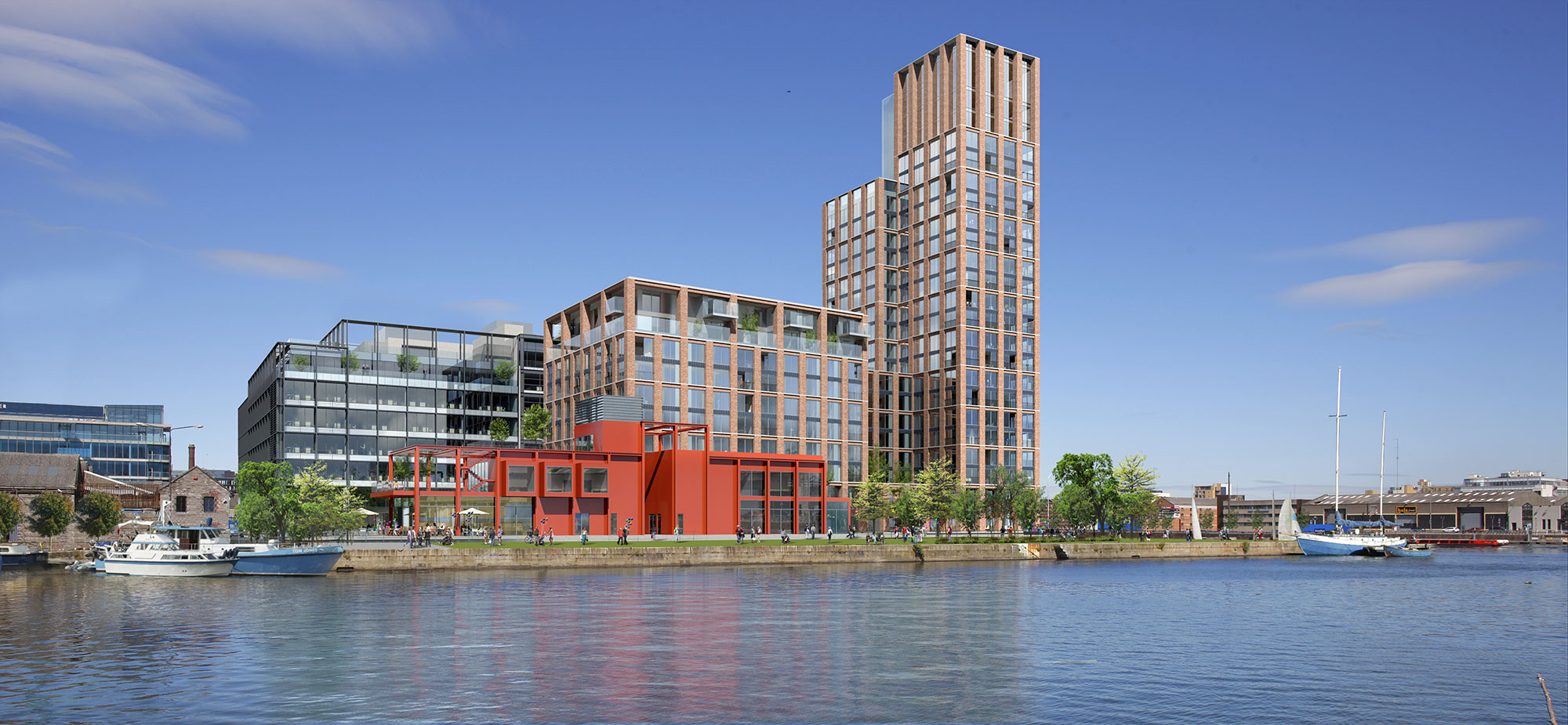
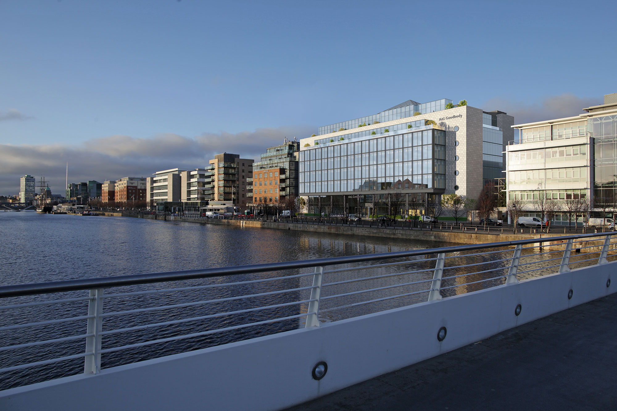
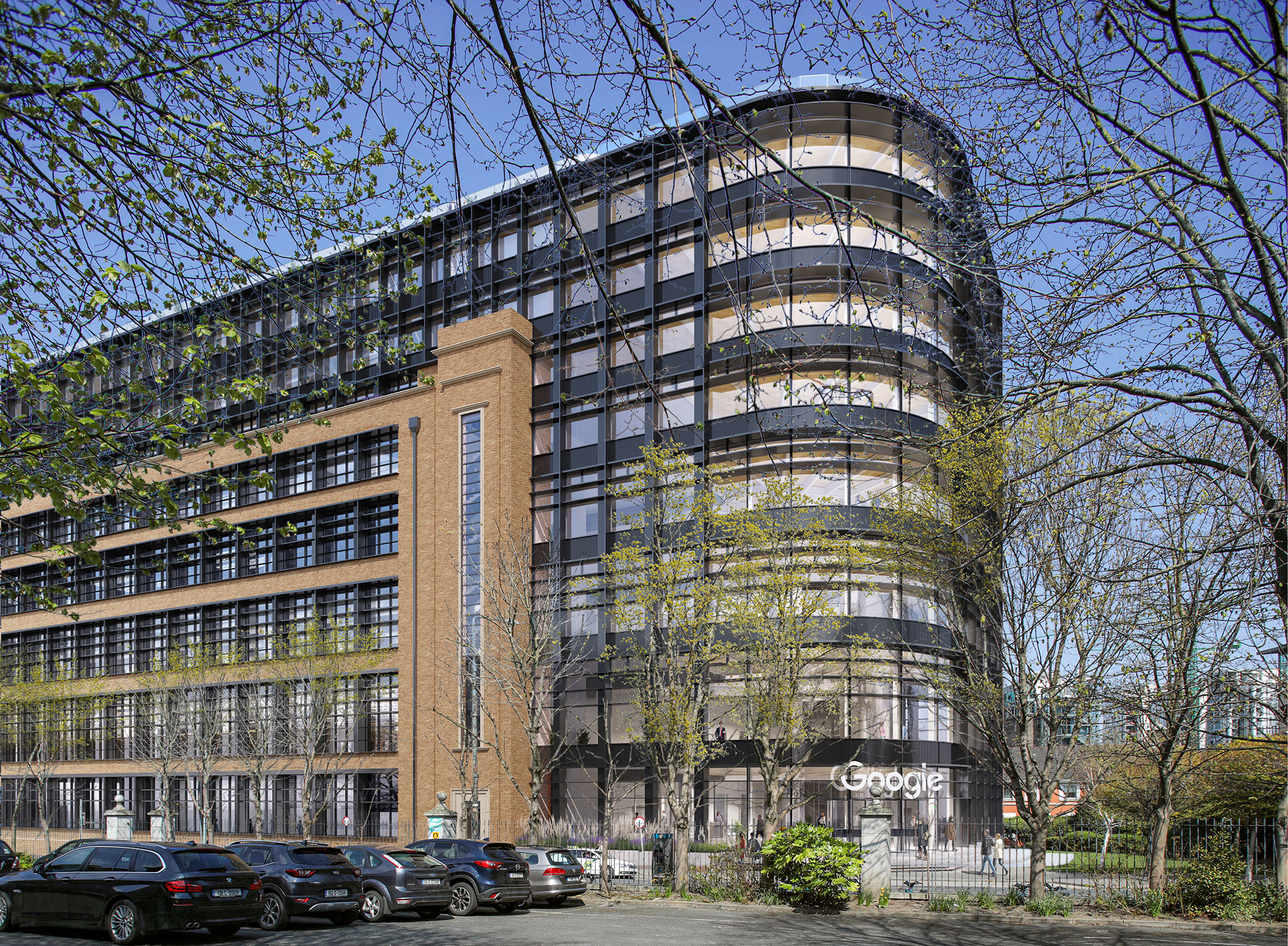
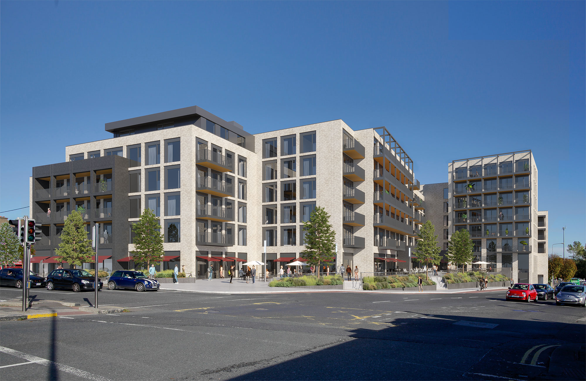
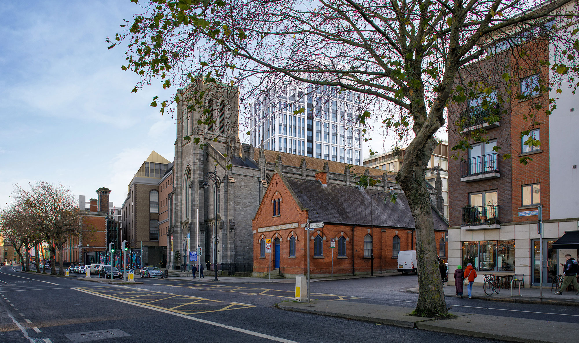
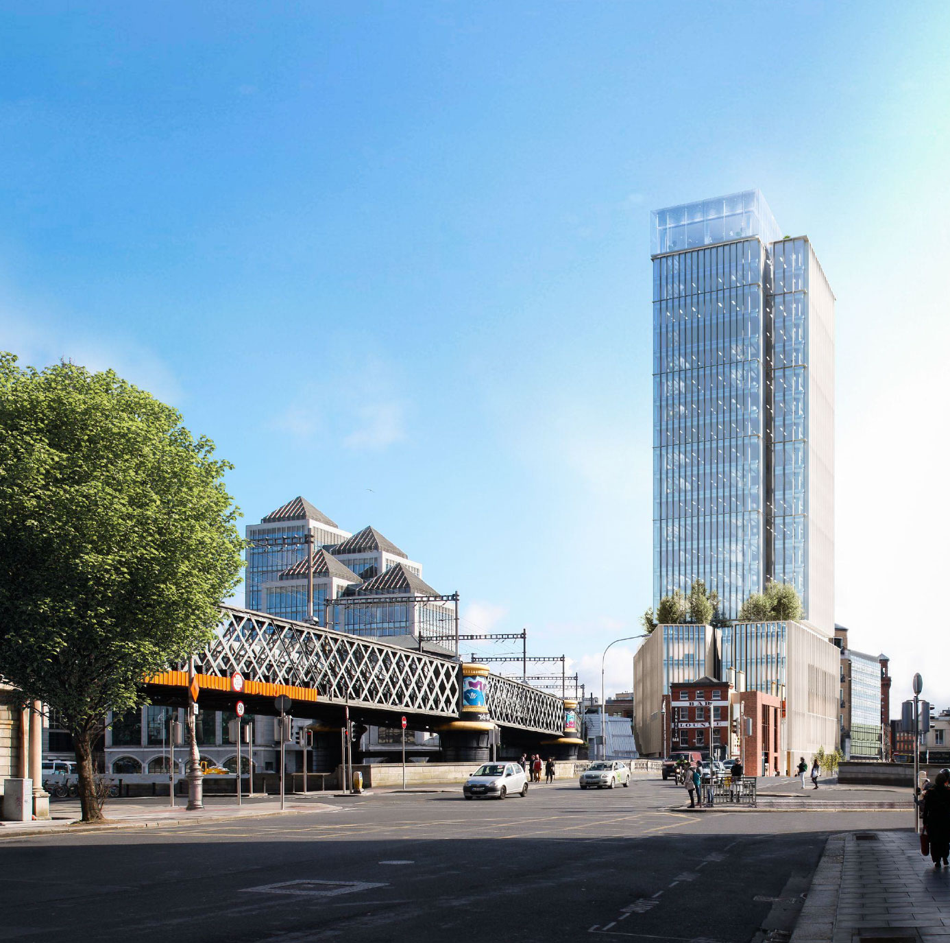
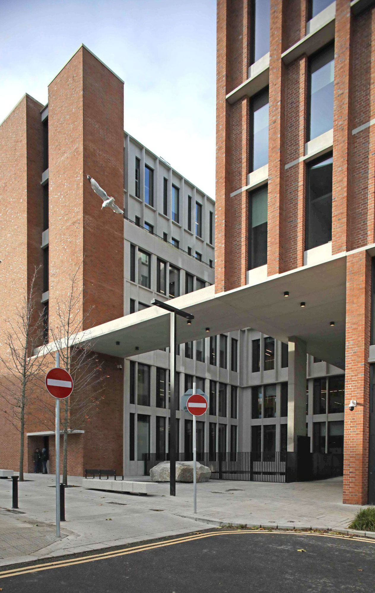
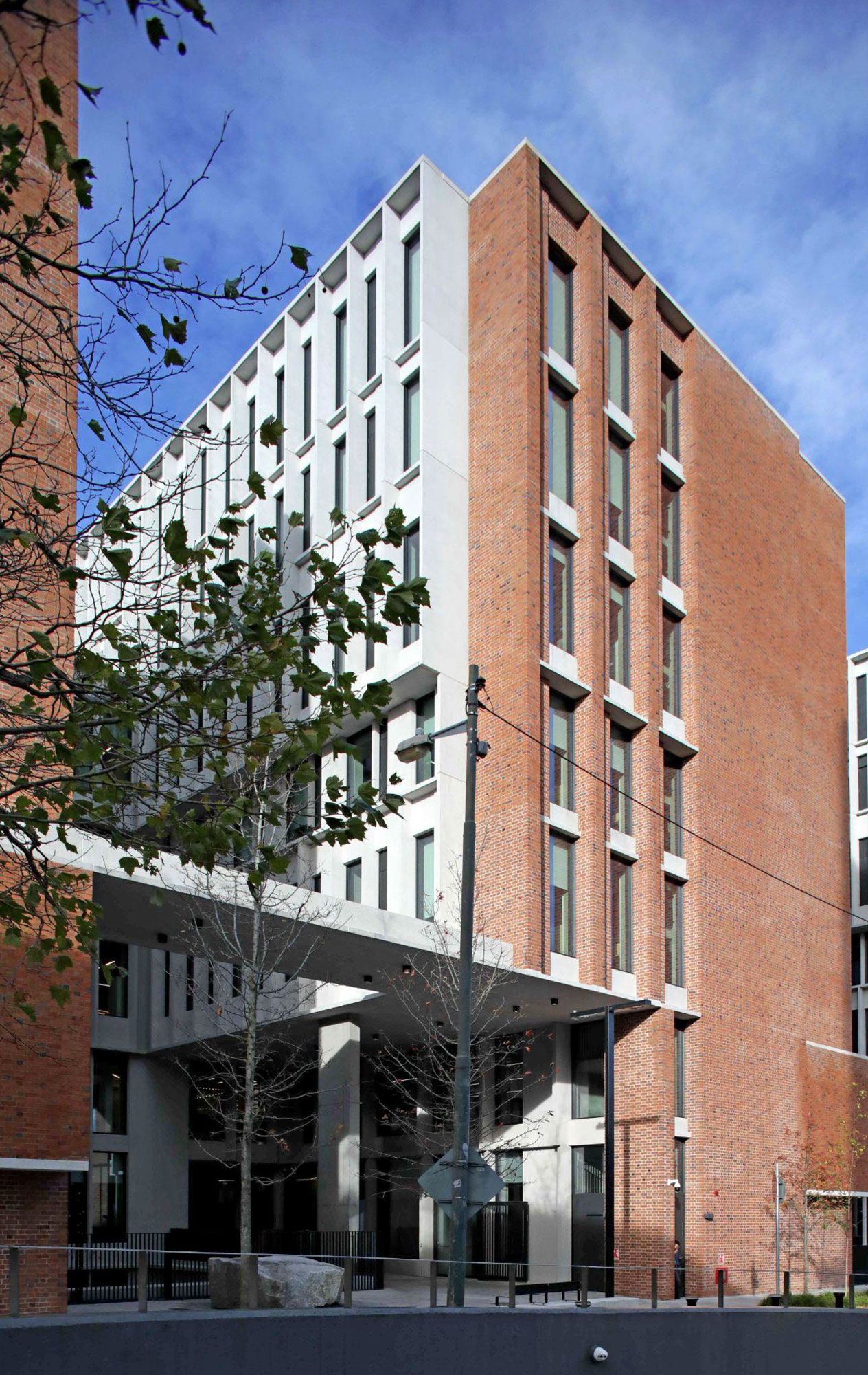
AVR 3 - AVR 2 + Use of materials
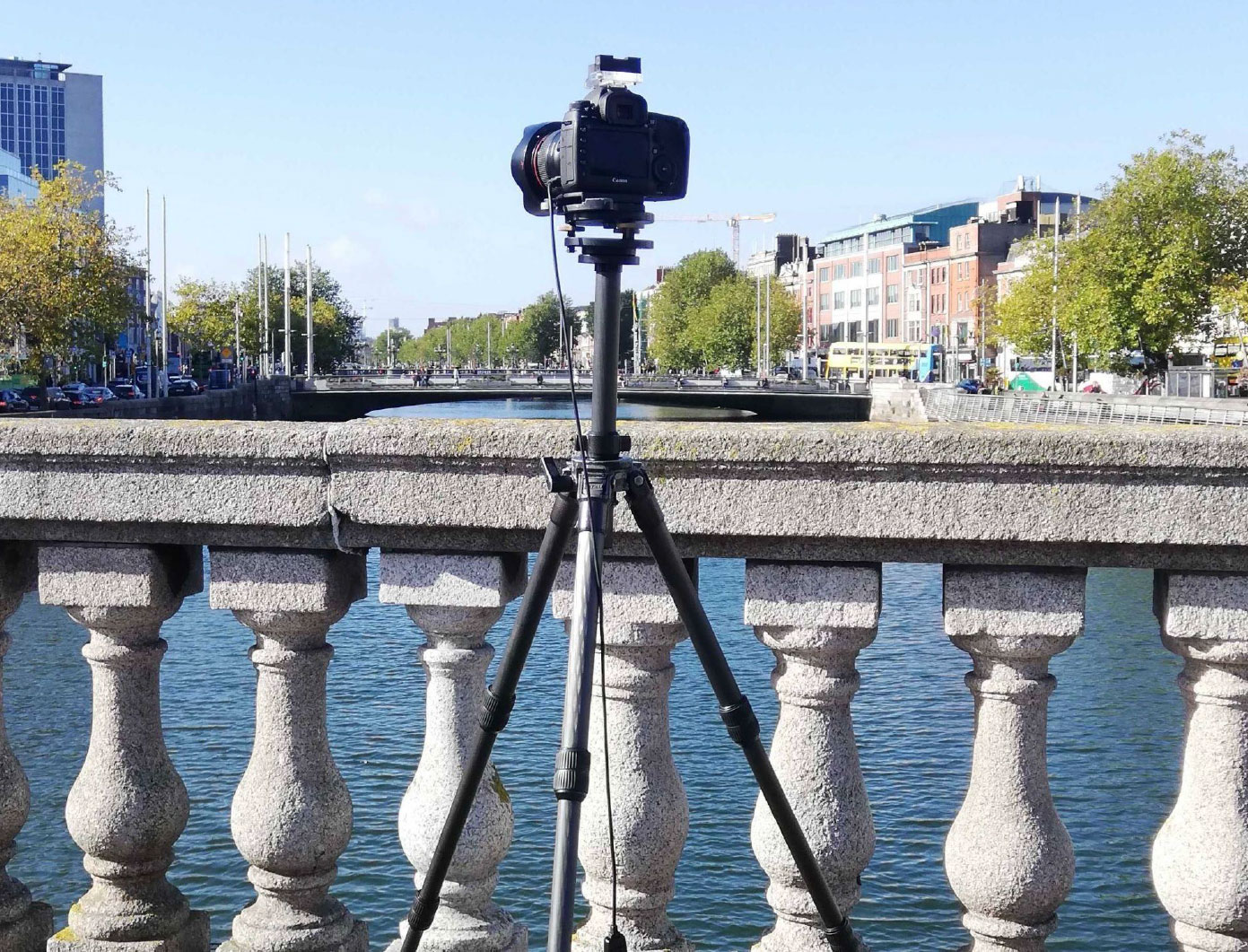

The Model Works methodology ensures that the representation is not only “robust” but is accurate, verifiable and auditable.
AVR 0 - Location and size of proposal
AVR 1 - AVR 0 + Visibility of proposal
AVR 2 - AVR 1 + Architectural form
AVR 3 - AVR 2 + Use of materials